
On smooth tube, cutting to length is a measurement problem. On corrugated tube it is a pattern problem: the same 300 mm can end on a crest, in a trough, or halfway up a wall.
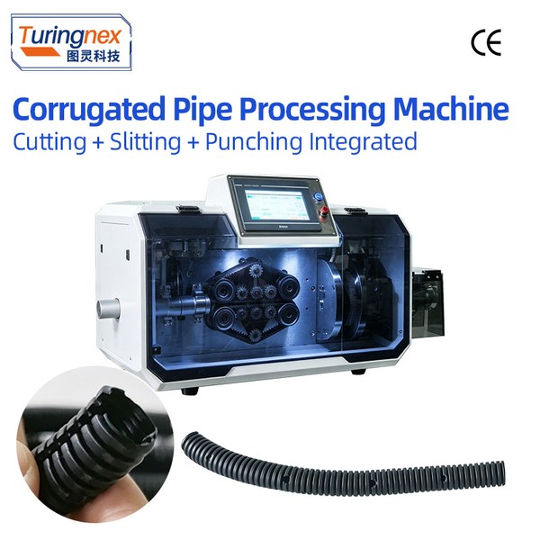
Why length alone is not enough
Corrugated tube is extruded with a repeating ring pattern. A cut that lands mid-wall leaves a thin, angled lip. Pushed into a connector or a clip, that lip folds rather than seats, and the joint leaks or pulls apart. Where an assembly calls for the cut to finish on a crest or in a trough, the position of the cut is a second tolerance stacked on top of the length tolerance.
A machine that only counts feed length cannot control that second tolerance, because the pattern does not start at a known point. The tube is fed from a reel or a box, and where the first crest falls depends on how it was cut last time.
What the camera actually does
A vision-positioning head looks at the tube just before the blade and finds the pattern. The controller then shifts the cut so that it lands on the feature that was selected — a peak, a trough or a joint.
The company specifies this on the TR-B30S, described as 'vision positioning captured by camera; can cut at specified positions: peaks, troughs, joints'. Variants add functions on top of the same head: the TR-B30SP adds slitting while cutting, and the TR-B30YTS adds a tube take-up so cut pieces are collected rather than dropped. A separate vision machine is offered for extensible tube and heat-shrink tubing, where the tube can be stretched and the pattern spacing is not fixed.
Getting the detection to work reliably
Vision on tube is a contrast problem, not a resolution problem. Three things decide whether it works on a customer's material:
- Colour. Black tube under white light gives almost no edge contrast. Ask for the lighting to be specified with the sample.
- Surface finish. Glossy tube produces a specular highlight that moves with the pattern and can be mistaken for a crest.
- Translucency. Thin-wall translucent tube shows the inside of the far wall as a second edge.
None of these is a reason to avoid vision cutting. All of them are reasons to send a sample rather than a drawing.
| Task | Straight cutting | Vision positioning |
|---|---|---|
| Cut to length only | Sufficient | Not needed |
| Cut must land on a crest or trough | Not achievable | Required |
| Cut at a joint or a moulded feature | Not achievable | Required |
| Extensible or heat-shrink tube | Unreliable (spacing varies) | Required |
| General nylon / rubber / silicone hose | Sufficient | Not needed |
Specifying it
State which feature the cut must finish on, and what departure is acceptable — one pattern pitch, half a pitch, or exact crest. Then give the tube outside diameter and wall thickness, whether it is cut from a reel or a box, and the required hourly rate. The camera has to see the tube while it is held, so clamping and detection are designed together.
If the cut position does not matter
Where the end is buried inside a connector shell and covered by tape or a boot, a standard TR-B30 will do the job and cost less. Vision positioning earns its place where the cut is visible, where it seals, or where the assembly is inspected. It is worth separating those two cases in a specification, because the price difference is significant and the benefit only applies to one of them.